
In the world of piping design engineering, precision and clarity are everything. Engineers, designers, and fabricators rely on accurate visual representations to transform intricate piping systems from concept to construction. Among the most essential tools in this process are isometric and orthographic pipe drawings—two distinct yet complementary drawing styles that bring mechanical systems to life.
At Mettler Design, these drawings aren’t just technical documents—they are visual blueprints that drive accuracy, coordination, and efficiency across every phase of a project.
What Are Isometric Pipe Drawings?
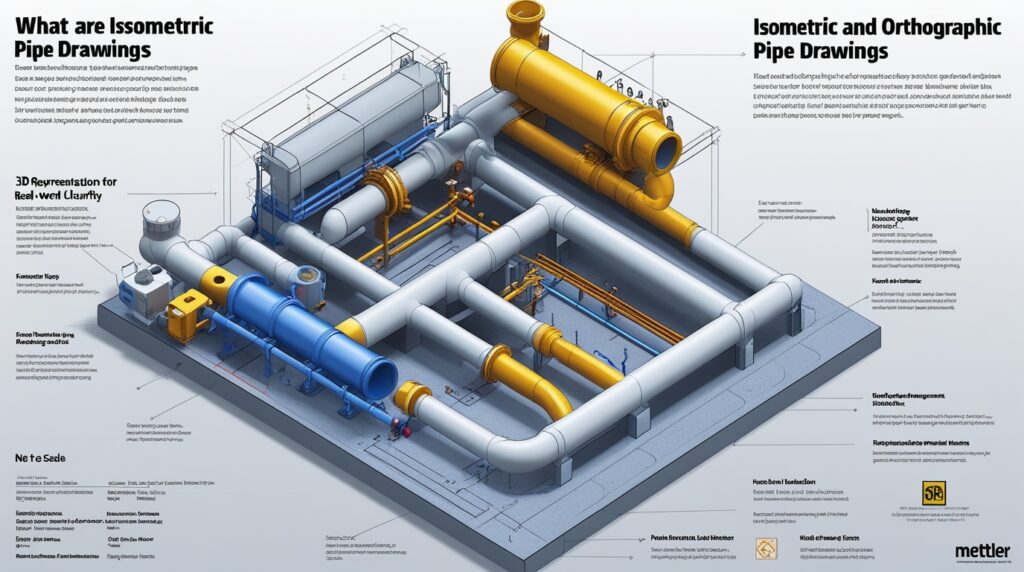
3D Representation for Real-World Clarity
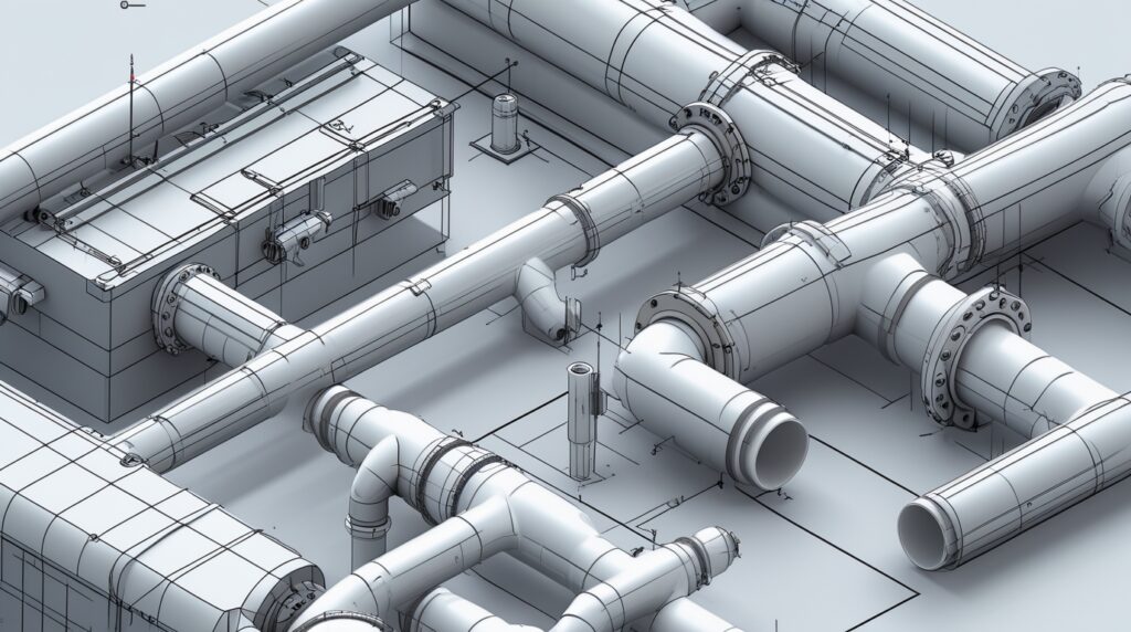
Isometric drawings are three-dimensional visualizations of piping systems presented on two-dimensional surfaces. They provide a realistic representation of how the system fits and flows within physical space. By angling all lines at 30 degrees, the drawing offers a 3D effect that shows height, width, and depth simultaneously.
Key Features of Isometric Pipe Drawings
- 3D Visualization: Offers a clear spatial understanding of the piping system layout.
- Ease of Interpretation: Field teams can visualize pipe routes and connections effectively.
- Comprehensive Detailing: Each pipe section includes precise measurements and flow directions.
- Not to Scale: Although dimensionally accurate, these drawings are typically not drawn to scale.
Common Uses
- Fabrication and installation
- Site layout and fieldwork planning
- Visual communication between design and construction teams
With Mettler Design’s expertise in 3D modeling and visualization, isometric pipe drawings become more than diagrams—they become the foundation for efficient project execution.
What Are Orthographic Pipe Drawings?
2D Accuracy for Technical Detailing
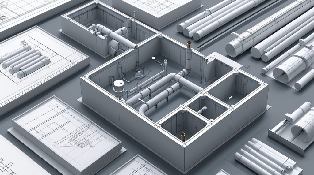
Unlike isometric drawings, orthographic drawings represent piping systems through multiple two-dimensional views—usually the top, front, and side. Each view provides exact measurements and relationships between components, allowing engineers to analyze and document technical details with high accuracy.
Key Features of Orthographic Drawings
- Multi-View Layouts: Depicts the front, top, and side planes for complete visibility.
- Precise Scaling: Every component is drawn to scale, making it perfect for documentation.
- Detailed Clarity: Displays accurate component placement and measurements.
- No Perspective: Focuses purely on dimensions without depth perception.
Common Uses
- Engineering design approvals
- Documentation and internal reviews
- Fabrication detailing and manufacturing processes
- Communication between multidisciplinary teams
When accuracy and documentation are top priorities, orthographic pipe drawings by Mettler Design provide the technical precision required for flawless engineering.
Isometric vs Orthographic Pipe Drawings: Key Differences
| Feature | Isometric Drawings | Orthographic Drawings |
|---|---|---|
| Dimension | 3D visualization | 2D views (top, front, side) |
| Purpose | Field installation and layout | Design documentation and review |
| Scaling | Not to scale | Drawn to exact scale |
| Interpretation | Easy for non-engineers | Technical accuracy for professionals |
| Perspective | Shows depth and height | No perspective, flat projection |
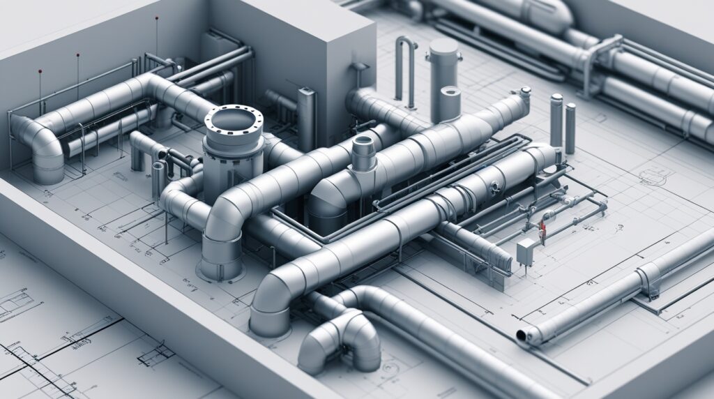
Understanding Why Both Are Essential
While isometric pipe drawings enhance visualization and on-site comprehension, orthographic drawings ensure technical accuracy and compliance. Together, they create a complete representation that enables designers, field technicians, and project managers to work in harmony.
Why the Difference Matters in Piping Design Engineering
Understanding the difference between isometric and orthographic drawings helps engineering teams maintain alignment from design to fabrication. Here’s how different roles benefit:
- Design Engineers use orthographic drawings for precise component placement.
- Field Technicians rely on isometric drawings for practical, on-site visualization.
- Project Managers coordinate both drawing types to prevent miscommunication and optimize project flow.
- Clients and Stakeholders get easily interpretable visuals that simplify complex systems.
At Mettler Design, we integrate both drawing types seamlessly within a unified workflow, ensuring that engineering intent perfectly matches field execution.
Choosing the Right Partner for Piping Design Engineering
Mastering the use of both isometric and orthographic pipe drawings is only half the battle. The real challenge lies in producing accurate, standards-compliant, and industry-ready drawings that support seamless project delivery.
That’s where Mettler Design stands apart.
With years of expertise in mechanical and piping design engineering, our team delivers high-precision isometric and orthographic drawings tailored to each project’s unique specifications. From 3D modeling to detailed documentation, we ensure every line drawn meets the highest benchmarks of accuracy, quality, and efficiency.
Final Thoughts
When comparing isometric vs orthographic pipe drawings, it’s not about which is better—it’s about using the right tool for the right purpose. Together, these drawing types form the backbone of modern piping design engineering, enhancing collaboration, precision, and project success.
Partner with Mettler Design today to elevate your piping and mechanical design workflows—where technical accuracy meets creative excellence in every project.
