
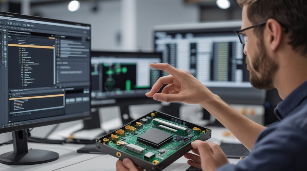
Designing intelligent, connected products has become the new standard across industries. However, as innovation accelerates, the product design process has grown more complex, especially when electronics and mechanical systems must work in perfect harmony. As a result, disconnected workflows between ECAD and MCAD teams often slow development, introduce errors, and increase costs.
At Mettler Design, we help engineering teams overcome these challenges by leveraging seamless ECAD MCAD integration using tools like SOLIDWORKS PCB. By unifying electrical and mechanical design in a single collaborative environment, companies can move faster, design smarter, and reduce costly rework.
In this blog, we explore how seamless ECAD/MCAD integration transforms modern product development—and why it’s essential for competitive, mechatronic products.
Why Seamless ECAD MCAD Integration Matters Today
Modern products are no longer purely mechanical or electrical. Instead, they are highly mechatronic, blending PCBs, enclosures, connectors, sensors, and embedded systems into a single design.
However, when ECAD and MCAD teams work in isolation, several issues arise:
- Connector misalignment
- Clearance and interference problems
- Late-stage redesigns
- Poor communication between teams
Fortunately, SOLIDWORKS ECAD/MCAD integration eliminates these problems by enabling real-time collaboration between PCB designers and mechanical engineers.
At Mettler Design, we see firsthand how this integration improves design accuracy and accelerates product development.
What Is Seamless ECAD/MCAD Integration?
Seamless ECAD MCAD integration allows electrical and mechanical design data to synchronize automatically, rather than relying on error-prone file imports and exports.
With SOLIDWORKS PCB, engineers can:
- Push PCB designs directly into SOLIDWORKS
- Pull mechanical changes back into the PCB layout
- Maintain a shared, real-time project database
- Track every engineering change order (ECO)
As a result, both teams work on the same live data, ensuring accuracy and alignment throughout the design cycle.
Full Schematic Capture and PCB Design in SOLIDWORKS PCB
Complete Electronic Design Capabilities
SOLIDWORKS PCB offers full schematic capture, enabling engineers to create:
- Electronic netlists
- Bills of materials (BOMs)
- Component definitions and parameters
- Multi-sheet and hierarchical schematics
Moreover, the intuitive interface—designed with SOLIDWORKS users in mind—makes navigation, component placement, and wiring fast and efficient.
Because everything links directly to the PCB layout, engineers move seamlessly from concept to manufacturing-ready designs.
Real-Time Collaboration Between ECAD and MCAD Teams
Push and Pull Without File Transfers
One of the most powerful features of seamless ECAD MCAD integration is real-time collaboration.
Instead of exporting STEP files or DXFs, engineers simply:
- Push PCB data to SOLIDWORKS
- Pull mechanical updates back into SOLIDWORKS PCB
Every change logs automatically, ensuring complete transparency and traceability.
At Mettler Design, this approach dramatically reduces miscommunication while improving design confidence.
3D PCB Visualization Enhances Mechanical Accuracy
True 3D Models for Better Fit and Function
SOLIDWORKS PCB is not just a 2D layout tool—it is a true 3D PCB design environment.
Engineers can:
- Switch instantly between 2D and 3D views
- Place components directly in 3D space
- Embed SOLIDWORKS part models, STEP files, or Parasolid files
- Create custom 3D models within the PCB tool
Because these 3D models synchronize directly with SOLIDWORKS, mechanical engineers always work with accurate geometry.
Solving Clearance and Interference Issues Early
Interference Detection in SOLIDWORKS
Once PCB data enters SOLIDWORKS, mechanical engineers can use powerful interference detection tools to identify problems early.
For example:
- Connectors colliding with chassis walls
- Components interfering with standoffs
- Misaligned board-to-board connectors
Instead of discovering these issues during prototyping, teams resolve them digitally—saving time and money.
Bidirectional Editing for Faster Iterations
Mechanical Changes Update the PCB Automatically
One major advantage of seamless ECAD MCAD integration is bidirectional editing.
Mechanical engineers can:
- Move connectors
- Adjust component placement
- Modify board outlines
- Add or reposition mounting holes
Once they push changes back, PCB designers see animated previews showing exactly what moved—and why.
Even better, routed traces remain electrically intact. The system simply creates new guide wires for cleanup, preserving design intent.
Designing Accurate Board Outlines in SOLIDWORKS
Complex Geometry Made Easy
Creating complex board outlines directly inside PCB tools can be difficult. However, SOLIDWORKS excels at precise geometry.
Using SOLIDWORKS, engineers can:
- Create accurate board outlines
- Add complex slots and cutouts
- Match enclosures with 100% accuracy
- Synchronize thickness based on PCB layer stack-ups
When these outlines push back into SOLIDWORKS PCB, the design remains perfectly aligned.
At Mettler Design, we frequently use this workflow for enclosure-driven PCB designs.
Managing Multi-Board and Mechatronic Assemblies
Modern products often include multiple PCBs within a single assembly.
Fortunately, SOLIDWORKS ECAD/MCAD integration supports:
- Multi-board projects
- Board-to-board connectors
- Rack-mounted systems
- Embedded electronics
Because every PCB appears as an intelligent SOLIDWORKS assembly—with reference designators intact—teams gain full visibility into the complete product architecture.
Accurate Manufacturing Outputs and Documentation
From Design to Production—Without Gaps
After finalizing the design, engineers can generate:
- NC drill files
- Manufacturing documentation
- Mechanical drawings
- Complete BOMs
Because electrical and mechanical data remain synchronized, manufacturers receive accurate, up-to-date information—reducing production delays and errors.
Why Mettler Design Recommends Seamless ECAD MCAD Integration
At Mettler Design, we specialize in advanced product development, CAD optimization, and engineering collaboration. We strongly advocate for seamless ECAD MCAD integration because it:
- Reduces costly redesigns
- Improves communication between teams
- Accelerates time to market
- Enhances product quality
- Supports scalable, intelligent product development
By leveraging SOLIDWORKS PCB and SOLIDWORKS Mechanical together, companies gain a competitive advantage in today’s fast-moving markets.
Final Thoughts: Design Smarter with Seamless ECAD MCAD Integration
As products grow smarter and more connected, traditional, disconnected workflows no longer work. Instead, engineering teams need real-time collaboration, accurate data exchange, and intelligent design tools.
Seamless ECAD MCAD integration using SOLIDWORKS PCB delivers exactly that.
If your organization is ready to streamline PCB and mechanical collaboration, eliminate rework, and accelerate innovation, Mettler Design is here to help.
