
Products are no longer simple or isolated systems. Instead, they are intelligent, connected, and highly mechatronic. As a result, engineers must design electronics and mechanical enclosures together—not separately. However, many teams still struggle because traditional workflows rely on file exports, manual updates, and disconnected tools.
This is where seamless ECAD MCAD integration becomes essential.
At Mettler Design, we understand that modern product development demands precise coordination between electrical and mechanical teams. Therefore, we leverage proven SOLIDWORKS-based workflows that allow real-time collaboration between PCB design and mechanical CAD. By doing so, we help businesses reduce errors, accelerate development, and deliver smarter products to market faster.
The Growing Complexity of Intelligent Product Design
Electronics and Mechanics Are No Longer Separate
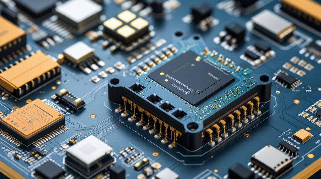
Today’s products integrate PCBs, connectors, sensors, and embedded electronics directly into mechanical enclosures. Consequently, even a minor mismatch—such as a misplaced connector or incorrect board outline—can cause costly redesigns.
Moreover, competition continues to rise. Companies must innovate faster while maintaining quality. Unfortunately, disconnected ECAD and MCAD workflows slow teams down and introduce avoidable risks.
That is exactly why seamless ECAD MCAD integration has become a critical success factor for modern engineering teams.
What Is Seamless ECAD/MCAD Integration?
A Unified Workflow for Electrical and Mechanical Teams
Seamless ECAD/MCAD integration allows PCB designers and mechanical engineers to work on the same design data in real time. Instead of exporting STEP files or exchanging static DXFs, teams push and pull live design updates between ECAD and MCAD environments.
With SOLIDWORKS PCB and SOLIDWORKS Mechanical CAD, engineers can:
- Share accurate 3D PCB data instantly
- Synchronize component placement and board outlines
- Detect interferences early
- Maintain full design intent across disciplines
At Mettler Design, we implement these workflows to ensure smooth collaboration throughout the entire product lifecycle.
Why Mettler Design Recommends SOLIDWORKS ECAD/MCAD Solutions
Designed for Mechatronic Products
SOLIDWORKS ECAD/MCAD solutions were built specifically for mechatronic products. Because modern devices combine electronics and mechanics, this ecosystem supports both domains equally.
More importantly, SOLIDWORKS PCB integrates directly with SOLIDWORKS Mechanical CAD. As a result, engineers work with real design data—not approximations.
Mettler Design helps clients adopt these tools effectively so teams can collaborate without friction.
Full Schematic Capture for Accurate PCB Design
From Concept to Manufacturing-Ready Designs
SOLIDWORKS PCB provides complete schematic capture capabilities. Engineers can easily create:
- Electrical schematics
- Netlists
- Bills of materials (BOMs)
- Component parameters and libraries
Once completed, the schematic connects directly to the PCB layout. Consequently, design intent remains consistent throughout the process.
At Mettler Design, we emphasize structured schematic development because it forms the foundation for reliable PCB and mechanical collaboration.
Real-Time Collaboration Between ECAD and MCAD
Push-and-Pull Design Synchronization
One of the most powerful aspects of seamless ECAD MCAD integration is real-time collaboration. Engineers no longer rely on file imports and exports. Instead, they push updates directly to a shared database.
For example:
- PCB designers push the board to SOLIDWORKS
- Mechanical engineers pull the board into assemblies
- Changes flow back instantly to the PCB tool
This approach dramatically reduces miscommunication and design rework.
3D PCB Visualization Enhances Mechanical Accuracy
Designing with True 3D Data
SOLIDWORKS PCB is not limited to 2D layouts. Instead, it includes full 3D visualization. Engineers can switch instantly between 2D and 3D views while placing components.
Additionally, PCB footprints contain embedded 3D models. These models collaborate directly with SOLIDWORKS assemblies. As a result, mechanical engineers see exactly how components fit inside enclosures.
Mettler Design relies on this capability to ensure clearance accuracy and proper connector alignment early in the design phase.
Improving Connector Placement and Clearance
Detect Issues Before Manufacturing
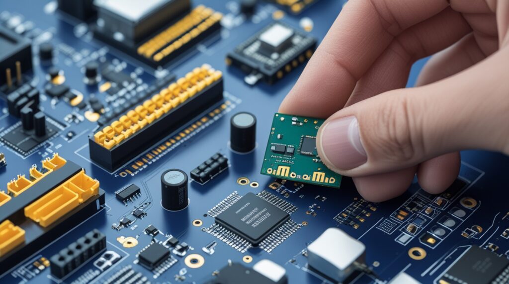
Connectors often cause integration challenges. Even small placement errors can lead to assembly failures. Fortunately, seamless ECAD MCAD integration eliminates guesswork.
Mechanical engineers can:
- Assemble multiple PCBs
- Align board-to-board connectors
- Check interference using SOLIDWORKS tools
When conflicts appear, engineers adjust components directly in SOLIDWORKS and push updates back to the PCB design. The PCB tool then visualizes these changes with animation, ensuring clarity before acceptance.
This workflow saves time and prevents costly redesigns.
Creating Accurate Board Outlines Using SOLIDWORKS
Mechanical Precision Meets PCB Design
Complex board outlines are difficult to create in traditional ECAD tools. However, SOLIDWORKS excels at precise mechanical sketching.
With ECAD/MCAD collaboration:
- Mechanical engineers define board outlines in SOLIDWORKS
- Slots, cutouts, and arcs remain 100% accurate
- PCB tools receive the updated geometry instantly
At Mettler Design, we often recommend this approach for products with tight mechanical constraints or custom enclosures.
Managing Multi-Board Assemblies with Ease
Scalable Collaboration for Complex Products
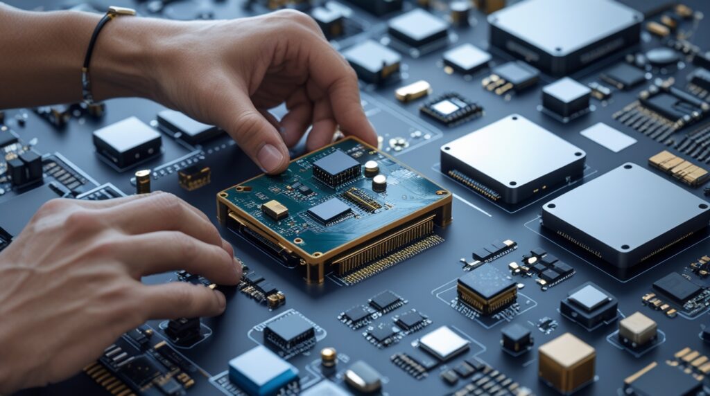
Many modern products include multiple PCBs. Fortunately, seamless ECAD MCAD integration supports multi-board assemblies.
Engineers can:
- Load multiple boards into one SOLIDWORKS assembly
- Align them with enclosures and chassis
- Verify spacing, mounting holes, and connectors
Because updates synchronize in real time, teams maintain design integrity across all boards.
Smart Handling of Mounting Holes and Mechanical Changes
Direct Correlation Between CAD and Manufacturing
Another major advantage is how mounting holes behave across ECAD and MCAD environments. When mechanical engineers move or resize holes in SOLIDWORKS, those changes automatically update PCB drill data.
This direct correlation ensures:
- Accurate NC drill files
- Consistent manufacturing output
- Reduced communication gaps
Mettler Design leverages this capability to streamline production-ready designs.
Faster Design Cycles and Fewer Errors
The Business Impact of ECAD/MCAD Integration
Seamless ECAD MCAD integration delivers tangible benefits:
- Faster time to market
- Fewer design iterations
- Lower manufacturing risks
- Improved cross-team collaboration
Most importantly, teams gain confidence in their designs before release.
By adopting these workflows, Mettler Design helps organizations remain competitive in fast-moving markets.
Why Choose Mettler Design for ECAD/MCAD Integration
At Mettler Design, we combine engineering expertise with proven SOLIDWORKS workflows. We do not just design products—we design efficient processes.
Our approach ensures:
- Seamless collaboration between electronics and mechanics
- Accurate 3D data throughout development
- Optimized PCB and enclosure integration
- Scalable solutions for complex products
By implementing seamless ECAD MCAD integration, we help clients build smarter, faster, and more reliable products.
Final Thoughts: Designing the Future with Confidence
As products become more intelligent and connected, engineering workflows must evolve. Disconnected tools and manual processes no longer suffice. Instead, real-time collaboration between ECAD and MCAD is essential.
Seamless ECAD MCAD integration—powered by SOLIDWORKS and implemented by Mettler Design—transforms how teams design, collaborate, and innovate.
If you want to eliminate errors, accelerate development, and deliver high-quality mechatronic products, now is the time to embrace integrated design workflows with Mettler Design.
